There is a quality inspection station somewhere on almost every manufacturing floor — a person or a small team, standing under bright lights, examining parts as they pass by on a conveyor. They look for surface cracks, dimensional deviations, colour inconsistencies, and foreign material inclusions. They are experienced, they care about their work, and they are also human — which means their performance varies across shifts, degrades with fatigue, and cannot scale without adding headcount.
Industrial computer vision systems are changing this — not by replacing the expertise that goes into defining what a good part looks like, but by applying that expertise consistently and tirelessly at line speed, on every part, across every shift. Modern defect detection models are accurate enough, inference hardware is fast enough, and integration tooling has matured enough that machine vision for quality control is no longer a research project. It is a deployment decision.
Why Manual Quality Inspection Has a Performance Ceiling
Manual visual inspection is not just slow — it has a performance ceiling that no amount of training or process improvement can push through. Human inspectors typically catch between seventy and eighty-five percent of defects under ideal conditions. Under real production conditions — high throughput, repetitive tasks, end-of-shift fatigue, variable lighting — that figure drops further. Meanwhile, a missed defect on a safety-critical component or a cosmetic reject that reaches the customer carries consequences that compound quickly: warranty claims, production stoppages, customer attrition, and in regulated industries, compliance exposure.
The throughput constraint is the other hard limit. A person can only inspect so many parts per minute before the inspection becomes cursory. Lines that run faster than a careful human can comfortably inspect tend to compensate by sampling — checking every fifth or tenth part rather than every part — which means statistically poor batches can pass through undetected. Computer vision systems inspect every unit at full line speed without sampling.
How Computer Vision Defect Detection Models Work
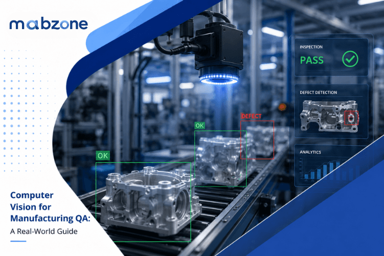
The core of a computer vision QA system is an image classification or object detection model — typically a convolutional neural network or a transformer-based vision model — trained on labelled examples of acceptable and defective parts. At inference time, images captured by line cameras are passed to the model in milliseconds, and the model returns a classification along with a confidence score and, for object detection models, localisation of the defect region within the image.
Modern pre-trained models — trained on millions of general images — provide a starting point that dramatically reduces the labelled data requirement for industrial fine-tuning. A well-executed fine-tuning run on a few thousand labelled examples of your specific parts and defect types can produce a model that outperforms manual inspection on the defect categories it has been trained to recognise. Anomaly detection approaches, which learn the distribution of good parts without requiring labelled defect examples, are particularly valuable in early deployments where defect data is scarce.
The model is not the hard part. The hard part is everything around it.
Industrial Camera Setup and Lighting: The Critical Foundation
The single most common reason computer vision pilots fail to translate into production systems is physical setup — camera placement, lens selection, and lighting configuration that works well in controlled conditions but produces inconsistent image quality when installed on the line.
Defect visibility depends entirely on the interaction between the part surface, the light source, and the camera angle. A surface crack that is obvious under raking light at a fifteen-degree angle becomes invisible under diffuse overhead illumination. A colour deviation that is clear on a calibrated monitor disappears when the ambient factory lighting changes with the time of day. These are not software problems. They are optical engineering problems that must be solved in the physical installation before any model can be expected to perform reliably.
Successful deployments invest seriously in this phase: working with industrial lighting specialists, running controlled experiments with different illumination geometries, selecting industrial cameras with appropriate resolution and global shutter characteristics for the line speed, and fixing the installation rigidly enough that vibration and thermal expansion do not shift the field of view over time. Getting this right is tedious and slow. It is also the foundation on which everything else depends.
Integrating Computer Vision With PLC, SCADA, and MES Systems
A computer vision system that can detect defects but cannot act on that detection within the window available on a moving line is only half a solution. The detection signal needs to connect to something — a diverter that physically removes the flagged part from the conveyor, a signal to the line PLC that triggers a stop, an alert to the quality station that a human review is required, or a combination of all three depending on the confidence score and defect severity.
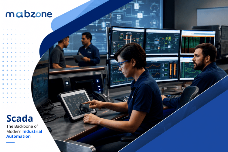
This integration work sits at the boundary between the computer vision system and the existing production control infrastructure, which typically means interfacing with PLCs, SCADA systems, and MES platforms that were not designed with AI systems in mind. The latency budget is tight: on a line running at speed, the time between detection and the physical rejection point may be measured in fractions of a second. The integration must be reliable enough that the line team trusts the system — a false positive that stops the line unnecessarily, or a missed detection that lets a flagged part through, erodes confidence faster than it is built.
Start Small: The Incremental Computer Vision Deployment Strategy
The deployments that succeed consistently share a common approach: they start narrow. Rather than attempting to detect every defect category from day one, they identify the single defect type that causes the most production cost or customer impact, deploy the computer vision system for that one category, and validate its performance carefully before expanding scope.
This approach serves multiple purposes. It gives the engineering team a controlled environment in which to learn the physical and integration challenges specific to their line. It generates a clear, auditable performance record that builds trust with the quality team and plant management. And it creates a concrete ROI case that justifies the investment in expanding the system to additional defect categories and additional stations.
The expansion phase is typically much faster than the initial deployment. The camera infrastructure is in place, the integration patterns are established, and the team has developed the domain knowledge to label new defect categories efficiently. A system that started detecting one defect type on one line can grow to cover a full quality gate across multiple lines within a year, with each expansion building on the foundation of the one before.
Monitoring Computer Vision Model Performance in Production
Production computer vision systems need ongoing performance monitoring that goes beyond the metrics captured during initial validation. Model performance can drift as part designs evolve, as raw material suppliers change, as line conditions shift seasonally, or as the model encounters defect patterns that were not represented in the training data.
Effective monitoring means sampling a fraction of the system's decisions — both accepted and rejected parts — and routing them for human review on a continuous basis. This provides a ground truth comparison that surfaces performance degradation before it reaches the scale where defective products are reaching customers. It also generates a stream of new labelled data that feeds continuous model improvement, creating a feedback loop that makes the system more capable over time rather than static.
Computer Vision ROI: The Manufacturing Business Case
The ROI calculation for industrial computer vision rests on three value categories: defect escape reduction, scrap and rework reduction, and throughput improvement from removing the inspection bottleneck. In most deployments, defect escape reduction alone — fewer warranty claims, customer returns, and compliance incidents — justifies the system cost within eighteen months.
The throughput argument is compelling at facilities where manual inspection is the pacing constraint. Removing the inspection bottleneck increases effective throughput without adding equipment — the same line, producing more good units per shift because inspection no longer sets the pace.
At mabzone Technologies, we design and deploy computer vision quality systems from camera selection and lighting configuration through model development, PLC integration, and production monitoring infrastructure. If you are evaluating machine vision for your manufacturing QA line, we would be glad to walk through what a phased deployment would look like for your specific defect profile.
Frequently Asked Questions
What is computer vision in manufacturing quality control? Computer vision for manufacturing QA uses cameras and AI image-classification or object-detection models to inspect products on a production line, identifying defects such as surface cracks, dimensional deviations, and contamination faster and more consistently than human inspectors.
How accurate is computer vision defect detection compared to manual inspection? Human inspectors typically achieve 70–85% defect detection accuracy under ideal conditions. Well-trained computer vision models routinely exceed 95% accuracy on the defect categories they are trained for, and they maintain that accuracy consistently across all shifts without fatigue.
What is the difference between image classification and object detection in industrial QA? Image classification assigns a single label to the entire image (pass or fail). Object detection also localises the defect — identifying its position and size within the image. Object detection is more useful when defect location matters for downstream decisions such as targeted rework.
How do computer vision systems integrate with PLCs and SCADA? Computer vision systems generate a classification signal (pass, fail, or review) that is sent to the line PLC via industrial communication protocols such as OPC-UA, Modbus, or discrete I/O. The PLC then triggers the appropriate physical response — a diverter, a line stop, or an alert — within the available latency window.
What is the typical payback period for a computer vision QA system? Most industrial computer vision deployments achieve payback within 12–24 months, primarily through reduction in warranty claims, rework costs, and in some cases throughput improvements from removing the manual inspection bottleneck.